DFP5043 – Software
Requirement and Design
Tutorial Lab4
Instruction:
Discuss and contribute
together to answer
the questions below and
post the answer to the class's blog.
Don't forget to write
your name in the blog.
Define and draw example
of architectural design and models of software architecture below:
i. Architectural Design
ii. Logical View
iii. Process View
iv.
Development View
v.
Physical View
vi.
Scenario
- Architectural Design
An architectural model is a rich and rigorous diagram, created using available standards, in which the primary concern is to illustrate a specific set of tradeoffs inherent in the structure and design of a system or ecosystem. Software architects use architectural models to communicate with others and seek peer feedback. An architectural model is an expression of a viewpoint in software architecture.

- Logical View

- Process View
The process view addresses concurrency, distribution, integrators, performance, and scalability, etc. UML diagrams to represent process view include the activity diagram.
Activity diagrams are graphical representations of workflows of stepwise activities and actions with support for choice, iteration and concurrency.
In the Unified Modelling Language, activity diagrams are intended to model both computational and organizational processes (i.e., workflows), as well as the data flows intersecting with the related activities. Although activity diagrams primarily show the overall flow of control, they can also include elements showing the flow of data between activities through one or more data stores
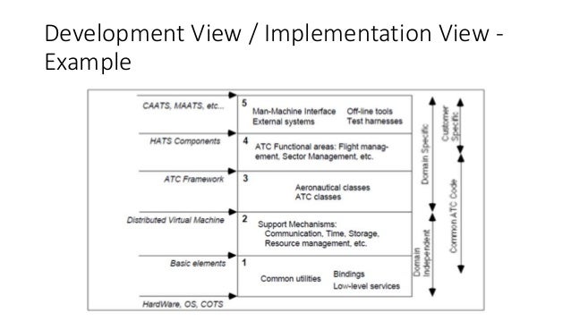
- Development View
|
Definition
|
Describes the architecture that supports the software development
process.
|
|
Concerns
|
|
|
Models
|
|
|
Pitfalls
|
|
|
Stakeholders
|
Production engineers, software developers and testers.
|
|
Applicability
|
All systems with significant software development involved in their
creation.
|
- Physical View

- Scenario
The description of an architecture is illustrated using a small set of use cases, or scenarios, which become a fifth view. The scenarios describe sequences of interactions between objects and between processes. They are used to identify architectural elements and to illustrate and validate the architecture design. They also serve as a starting point for tests of an architecture prototype. This view is also known as the use case view. The following diagram is the use case view.

Overall:

GROUP 1:
- ARIF ASNAWI BIN MOHD PAUZI (01DIS17F1047)
- MUHAMMAD FARID BIN MOHD ARIFFIN (01DIS17F1041)
- MUHAMMAD AKMAL BIN AHMAD FADZIL (01DIS17F1040)
- ABDUL RAHMAN BIN MESRUN (01DIS17F1061)
- MUHAMMAD HASNUDDIN BIN SALAHUDDIN (01DIS17F1062)
- MUHAMMAD AMIRUDDIN BIN ABDUL KADIR (01DIS17F1034)
- MUHAMMAD HAFIZ BIN ZUHARI (01DIS17F1037)
- AHMAD THAQIF ILMAM BIN ABDUL AZIZ (01DIS17F1035)
- NURUL IZZAH BINTI KAMAL FAISAL (01DIS17F1049)
- MIMI AMIRAH BINTI CHE ABDUL (01DIS17F1045)
- NUR AFIQAH BIN MOHAMAD RAMLEE (01DIS171057)
- KU NURAL' IZZATI BINTI KU KAMARUDZAMAN (01DIS17F1064)
- NURUL ELISYAH BINTI MUHAMMAD ARSHAD (01DIS17F1033)
- YASHELA A/P CHANDRANSANGRAN (01DIS17F1101)


No comments:
Post a Comment